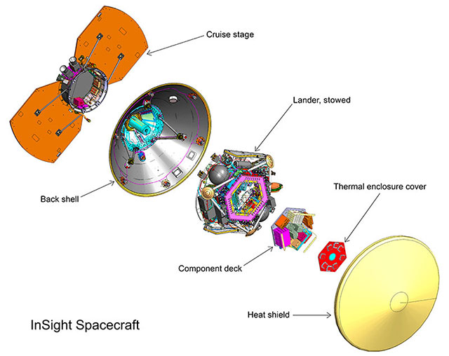
The lander is the core of the InSight spacecraft. Not only will it be the element carrying out all of the activity on Mars, its computer also controls functions of the three secondary elements of the flight system: the cruise stage, back shell and heat shield.

The InSight spacecraft is based on the design of NASA’s 2007-2008 Phoenix Mars Lander, with updates to accommodate InSight’s unique science payload and new mission requirements. Some key functions and features of the InSight spacecraft are power, communications, command and data handling, propulsion, guidance and thermal control.

Lockheed Martin Space in Denver designed, built and tested the InSight spacecraft. Lockheed Martin Space previously delivered the Phoenix spacecraft and all three NASA orbiters currently active at Mars: Mars Odyssey, Mars Reconnaissance Orbiter and Mars Atmosphere and Volatile Evolution (MAVEN).

illustration

The InSight flight system comprises the lander, with its component deck and thermal enclosure cover, encapsulated in the aeroshell formed by the back shell and heat shield, and topped by the cruise stage. Credit: NASA/JPL-Caltech/Lockheed Martin Space
Download image

Lander

The InSight lander will face south and the mission’s workspace will be the ground within reach of the robotic arm on the south side of the lander. Because the site is north of the equator, this will prevent the lander’s shadow from passing over deployed instruments. The lander’s two solar arrays will extend like circular wings east and west from the central deck, with a wingspan of 19 feet, 8 inches (6 meters). Front to back, the lander is 8 feet, 10 inches (2.7 meters) deep. The top of the deck will be 33 to 43 inches (83 to 108 centimeters) above Martian ground level, depending on how far the three shock-absorbing legs compact after the landing. With its solar panels deployed, the lander is about the size of a big 1960s convertible.
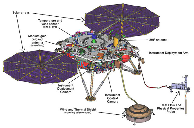
Illustration of the InSight lander's deployed configuration.

In this illustration of the InSight lander’s deployed configuration, south would be toward lower right at the Martian work site, with tethered instruments on the ground and the heat probe’s mole underground. Credit: NASA/JPL-Caltech/Lockheed Martin Space Download image

The lander’s panels are based on the design of those flown on NASA’s Mars Phoenix Lander, though InSight’s were made slightly larger for more power output and to increase structural strength. These changes were required to support the two-year landed prime science mission with sufficient margins (two Earth years, one Mars year).

Hardware on top of the deck includes the robotic arm, two dedicated science instruments and their accessories, a laser reflector, a helical UHF antenna and two X-band antennas (which are also used as part of a science experiment). In the weeks after landing, the arm will lift the seismometer, its Wind and Thermal Shield and the thermal probe from the deck and place them onto the Martian surface.

The lander’s avionics are mounted to a component deck located within a thermally protective enclosure. This suite of electronics consists of the flight computer, the electrical power system, the landed telecommunications system, the payload electronics and the harness. Other components, such as the inertial measurement units, radiometer, magnetometer and landing radar, are externally mounted under the science deck. Thrusters extend from the sides of the lander.
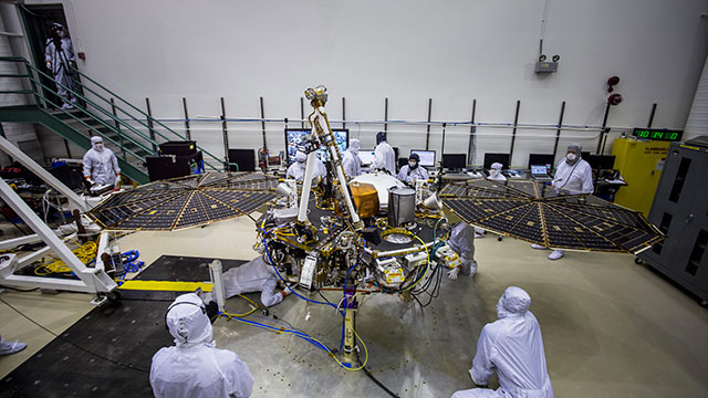
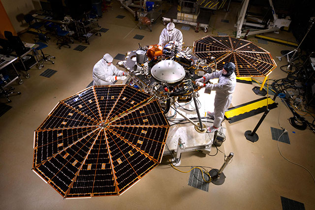
Engineers at Lockheed Martin Space, Denver, test the solar arrays on NASA’s InSight lander

Engineers at Lockheed Martin Space, Denver, test the solar arrays on NASA’s InSight lander several months before launch. Credit: NASA/JPL-Caltech/Lockheed Martin Space


Instrument Deployment System: One Arm and Two Cameras

The lander’s Instrument Deployment System (IDS) has a robotic arm for moving instruments from the deck onto the ground and two color cameras for finding the best place to put them and documenting the process. One of the cameras is mounted on the arm; the other on the front of the lander, beneath the south edge of the deck.

The Instrument Deployment Arm (IDA) includes a grapple for grasping each piece of hardware that the arm will lift. The grapple’s five mechanical fingers can close around a handle that resembles a ball on top of a stem. Each of the three items that the arm will lift has one of these handles. The three items are the Seismic Experiment for Interior Structure (SEIS), the Heat Flow and Physical Properties Probe (HP³), and the seismometer’s Wind and Thermal Shield. The arm is 5.9 feet (1.8 meters) long, with shoulder, elbow and wrist joints and four motors. The grapple is at the end of the arm. The arm-mounted camera is between the elbow and wrist.

The camera on the arm is called the Instrument Deployment Camera (IDC). The lander’s other camera, the Instrument Context Camera (ICC), is mounted just below the deck, on the edge of the lander facing the workspace, which is the area of ground within reach of the arm. Both are modified versions of engineering cameras on NASA’s Mars rovers Opportunity and Curiosity, with full-color capability added. Each has a square charge-coupled device (CCD) detector that is 1,024 pixels by 1,024 pixels.

The IDC’s field of view is 45 degrees wide and tall. Movement of the arm is used to point the camera. The IDC will image the workspace in detail to support selection of the best specific locations for the deployed instruments. It will also image hardware to verify key steps are accomplished in the deployment process before proceeding to the next step. By moving the camera’s position between exposures, the IDC can create stereo views that provide three-dimensional information about the surrounding area. The camera can be pointed in any direction, so it can take images to be combined into a 360-degree panorama of the lander’s surroundings. The ICC has a “fisheye” field of view of 120 degrees. It will provide wide-angle views of the entire workspace. The basic structure of the robotic arm was originally built for a Mars lander planned for launch in 2001, but that mission was cancelled before launch. JPL refurbished and modified the arm for InSight, including the additions of a grapple and camera. JPL also developed the software for controlling the arm and built both of the Instrument Deployment System’s cameras.

NASA’s InSight mission tests an engineering version of the spacecraft’s robotic arm

NASA’s InSight mission tests an engineering version of the spacecraft’s robotic arm in a Mars-like environment at NASA’s Jet Propulsion Laboratory. The Instrument Deployment Camera is visible at the “elbow” of the arm.


Science Experiments

InSight will be using its science experiments to take the “vital signs” of Mars: its pulse (seismology), temperature (heat flow) and its reflexes (radio science). The Seismic Experiment for Interior Structure (SEIS), a seismometer that measures ground motions in a range of frequencies, features six sensors of two different types. Those sensors are mounted on a three-legged precision leveling structure inside a remote warm enclosure box. That combination will be set directly onto the ground, connected to the lander by a flexible tether containing power and data lines. Then an additional protective cover -- the Wind and Thermal Shield -- will be placed over it. The SEIS electronics box remains on the lander.

France’s national space agency, Centre National d’Études Spatiales (CNES), Paris, leads the consortium that provided SEIS. InSight’s second dedicated science instrument, Heat Flow and Physical Properties Probe (HP³, pronounced “H-P cubed”), will provide the first precise determination of the amount of heat escaping from the planet’s interior. InSight’s robotic arm will place the instrument on the ground, where a self-hammering mechanical mole will burrow to a depth of 10 to 16 feet (3 to 5 meters) over the course of about 30 days. InSight’s heat probe will penetrate more than 15-fold deeper beneath the surface than any previous hardware on Mars.

A science tether with temperature sensors connects the upper end of the mole to the HP³ support structure, which is on the Martian surface. An engineering tether connects HP³ support structure to the instrument’s back-end electronics box on the lander.

The HP³ investigation also includes a radiometer to measure ground-surface temperature near the lander based on its infrared brightness. The German Aerospace Center (Deutsches Zentrum für Luft- und Raumfahrt, or DLR), headquartered in Cologne, provided InSight’s Heat Flow and Physical Properties Probe.

A third science experiment, the Rotation and Interior Structure Experiment (RISE), does not have its own dedicated science instrument; instead, it uses InSight’s direct radio connection with Earth to assess perturbations of Mars’ rotation axis, which can provide information about the planet’s core. The tools for RISE are the X-band radio on the InSight lander and the large dish antennas of NASA’s Deep Space Network. The lander’s radio link to Earth will provide precise tracking of the location of one site on the surface as the planet rotates, throughout the course of a full Mars year.
Auxiliary Payload Sensor Subsystem

Sensors that measure the local magnetic field, wind, and atmospheric temperature and pressure are attached to the lander deck. Together, these are called the Auxiliary Payload Sensor Subsystem (APSS). The primary reason for including these instruments in the mission’s payload is to aid interpretation of seismometer data by tracking changes in the magnetic field or atmosphere that could cause ground movement otherwise mistaken for a seismic event. However, they can also serve on their own for other Mars science investigations.

The University of California, Los Angeles; Spain’s Center for Astrobiology (Centro de Astrobiología, or CAB), Madrid; and JPL contributed key parts of APSS.

Laser Retroreflector for Mars

A dome-shaped device, affixed to the top of the InSight lander’s deck, holds an array of eight special reflectors. This is the Laser Retroreflector for InSight (LaRRI), which is not part of the InSight mission’s own science investigations but may passively provide science value for a future Mars orbiter mission, with a laser altimeter making extremely precise measurements of the lander’s location.

Agenzia Spaziale Italiana (ASI), the national space agency of Italy, provided LaRRI.

For more in-depth information on InSight’s science payload and goals, go to the Science section.

Your Name Is on Its Way to Mars

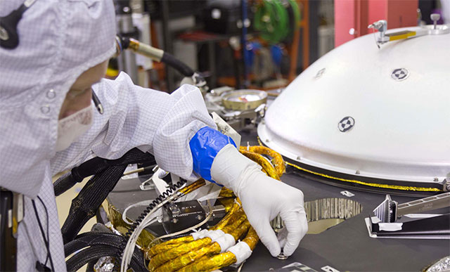
Another special feature on the deck of the lander is a pair of silicon chips etched with names of approximately 2.4 million people worldwide who participated in online “send your name to Mars” activities in August 2015 and 2017. Such activities are among many opportunities offered online for participation in Mars exploration. These chips are affixed near the northern edge of InSight’s deck.

A spacecraft specialist affixes onto the spacecraft deck one of the dime-size chips

A spacecraft specialist at Lockheed Martin Space in Denver, where InSight was built, affixes onto the spacecraft deck one of the dime-size chips, etched by NASA’s Jet Propulsion Laboratory with about 2.4 million names. Credit: NASA/JPL-Caltech/Lockheed Martin Space

Cruise Stage

InSight’s cruise stage will provide vital functions during the flight from Earth to Mars, and then will be jettisoned before the rest of the spacecraft enters Mars’ atmosphere. The core of the cruise stage is a short cylinder about 3 feet (0.95 meters) in diameter, with two fixed-wing solar panels extending out from the cylinder 180 degrees apart, for an overall wingspan of about 11 feet (3.4 meters), which is slightly larger than the wingspan of the world’s largest species of condor.

Equipment on the cruise stage includes low-gain and medium-gain antennas, an X-band transponder, two solid-state power amplifiers, two Sun sensors and two star trackers.


Back Shell and Heat Shield

The spacecraft’s back shell and heat shield together form the aeroshell that encapsulates the InSight lander from launch to the time the spacecraft is suspended on its parachute on its way to the Martian surface. The lander and aeroshell together, after separation from the cruise stage, are the entry vehicle. The back shell and heat shield are each conical in shape, meeting where the diameter is 8.66 feet (2.64 meters). The aeroshell’s height -- about 5.4 feet (1.6 meters) -- is about one-third heat shield and two-thirds back shell.

The spacecraft’s parachute and its deployment mechanism are stowed at the apex of the back shell. The parachute has a disk-gap-band configuration and a diameter of 38 feet, 9 inches (11.8 meters). Once deployed during descent, it will extend about 85 feet (26 meters) above the back shell. Pioneer Aerospace Corp. in South Windsor, Connecticut, made the parachute.

A UHF antenna for use during descent is wrapped around the top end of the back shell. At four locations around the back shell near its largest circumference, cutaways expose thrusters mounted on the lander. These are the eight thrusters used during the cruise from Earth to Mars. Each of the four cutaways accommodates one trajectory correction maneuver thruster and one reaction control system thruster.

The heat shield is covered with material that ablates away during the period of high-temperature friction with the Mars atmosphere, protecting the encapsulated lander from heat that is expected to rise as high as 2,700°F (1,500°C). This thermal protective system for InSight uses a material called super lightweight ablator 561, or SLA-561.

Electrical Power

InSight will use electrical power from solar panels, with batteries for storage, during cruise and after landing.

The fixed-wing photovoltaic panels on the cruise stage were built by Lockheed Martin Space in Sunnyvale, California, with triple-junction photovoltaic cells from SolAero Technologies Corp. in Albuquerque, New Mexico.

About 20 to 25 minutes after touchdown, the lander will deploy two nearly circular, 10-sided solar arrays, each 7.05 feet (2.15 meters) in diameter, extending from opposite sides of the lander. The two arrays combined have almost as much surface area as a pingpong table. Before landing, these are stowed in a radially folded configuration similar to a folded fan. After they have been deployed, the lander’s two arrays will together generate up to about 600 to 700 watts on a clear Martian day (or 200 to 300 watts on a dusty one). The UltraFlex panels are from Northrup Grumman Innovation Systems (formerly Orbital ATK-Goleta) in Goleta, California, with photovoltaic cells from SolAero.

A pair of rechargeable, 25 amp-hour lithium-ion batteries located on the lander will provide energy storage. The lithium-ion batteries are from the Yardney Division of EaglePicher Technologies in East Greenwich, Rhode Island. In addition, a single-use, non-rechargeable thermal battery will supplement the main batteries during entry, descent and landing.

illustration

The solar arrays on NASA’s InSight lander are deployed in this test in a clean room at Lockheed Martin Space, Denver, in April 2015. Each of the two arrays is 7.05 feet (2.15 meters) in diameter. Credit: NASA/JPL-Caltech/Lockheed Martin Space
Download image

Telecommunications

During the cruise from Earth to Mars, InSight will communicate with Earth using X-band antennas on the cruise stage. The cruise stage has a medium-gain, directional antenna and two low-gain antennas -- one for transmitting and the other for receiving. The spacecraft has one X-band small deep space transponder (SDST) on the lander and one on the cruise stage.

InSight, like all other NASA interplanetary missions, will rely on NASA’s Deep Space Network to track and communicate with the spacecraft. The network has groups of dish antennas at three locations: California, Spain and Australia. Additional communications support will be provided by the European Space Agency’s deep space antennas in Argentina and Australia while InSight is flying from Earth to Mars.

As InSight descends through the Martian atmosphere, it will be transmitting a signal in the ultrahigh frequency (UHF) radio band. The signal is generated by a UHF transceiver on the lander. That signal is transmitted by, first, a wrap-around patch antenna on the back shell and, later, after the lander separates from the back shell, by a helical UHF antenna on the lander deck.

For more on how these signals get back to Earth during entry, descent and landing, go to the Listening for InSight section. From the surface of Mars, InSight will use both X-band and UHF communications.

The primary method for sending data to Earth from the landing site will be via UHF relay to an orbiter, through the lander’s helical antenna. Mars Reconnaissance Orbiter and Mars Odyssey each will pass in the sky over InSight twice per Martian day. NASA’s MAVEN orbiter and the European Space Agency’s Trace Gas Orbiter and Mars Express can serve as backup relay assets for InSight. Orbiters will receive transmissions from InSight via UHF and relay the InSight data to Earth via X-band.

The lander’s own X-band communications will use a pair of medium-gain horn antennas on the deck, communicating directly with Deep Space Network antennas on Earth. In the planned orientation for the lander -- with the instrument workspace to the south for instrument deployment -- one X-band antenna faces eastward and the other westward. Viewing Earth from Mars is like viewing Venus from Earth: In either case, the inner planet is a morning or evening “star,” above the eastern horizon in morning or above the western horizon in the evening. The main uses for InSight’s X-band radio are the Rotation and Interior Structure Experiment (RISE) and for receiving commands directly from Earth.

Computer and Software

InSight’s system for command and data handling has avionics derived from NASA’s Mars Atmosphere and Volatile Evolution (MAVEN) and Gravity Recovery and Interior Laboratory (GRAIL) missions. The system has two redundant computers -- one active at all times and the other available as backup. The computer’s core is a radiation-hardened central processor with PowerPC 750 architecture called RAD 750. This processor operates at 115.5 megahertz speed, compared with 20 megahertz speed of the RAD6000 processor used on Mars Phoenix.

A payload interface card handles the processor’s interaction with InSight’s various science instruments and robotic arm. It provides 64 gigabits of flash memory for non-volatile storage of science data.

Flight software, written in C and C++ within the VxWorks operating system, monitors the status and health of the spacecraft during all phases of the mission, checks for the presence of commands to execute, performs communication functions and controls spacecraft activities. It will protect the spacecraft by checking commands for faults and being ready to take corrective steps when it detects irregularities in commanding or spacecraft health.

Propulsion

The propulsion for pushing InSight from Earth to Mars comes from the launch vehicle rather than the spacecraft itself, but the spacecraft carries 20 thrusters to control its orientation in space, to adjust trajectory as it coasts from Earth to Mars and to slow its final descent to the surface of Mars. The 20 thrusters are of three different sizes: four reaction control system (RCS) thrusters, each providing 1 pound (4.4 newtons) of force; four trajectory correction maneuver (TCM) thrusters, each providing 5 pounds (22 newtons) of force; and 12 descent engines, each providing 68 pounds (302 newtons) of force.

All of the thrusters are on the lander. The eight used while the lander is encapsulated inside the aeroshell extend out through cutouts in the back shell. One “rocket engine module” with one RCS thruster and one TCM thruster is at each of four cutouts around the back shell to allow maneuvers in any direction. The descent engines are on the underside of the lander, to be used for control of the lander’s descent during the last minute before touchdown. All of the thrusters use hydrazine, a propellant that does not require an oxygen source. Hydrazine is a corrosive liquid compound of nitrogen and hydrogen that decomposes explosively into expanded gases when exposed to a heated catalyst in the thrusters.

Guidance, Navigation and Control

InSight will remain oriented as it travels to Mars by using redundant pairs of star trackers and Sun sensors mounted on the cruise stage. A star tracker takes pictures of the sky and performs internal processing to compare the images with a catalog of star positions and recognize which part of the sky it is facing.

During descent through Mars’ atmosphere, the spacecraft’s knowledge of its movement and position will come from an inertial measurement unit, which senses changes in velocity and direction, and a downward-pointing radar to assess the distance and velocity relative to the Martian surface. The inertial measurement unit includes accelerometers to measure changes in the spacecraft’s velocity in any direction and ring-laser gyroscopes to measure how fast the spacecraft’s orientation is changing.


Thermal Control

InSight’s thermal control subsystem is a passive design supplemented with heaters. It uses multilayer insulation blanketing, other insulation, painted radiator surfaces, temperature sensors, heat pipes and redundant heaters controlled by thermostats. An enclosure for key electronics is designed to maintain component temperatures between 5°F (minus 15°C) and 104°F (40°C).

Science-payload components are thermally isolated from the lander and provide their own thermal control.

Planetary Protection

When sending missions to Mars, precautions must be taken to avoid introduction of microbes from Earth by robotic spacecraft. This is consistent with United States obligations under the 1967 Outer Space Treaty, the international agreement stipulating that exploration must be conducted in a manner that avoids harmful contamination of celestial bodies. “Planetary protection” is the discipline responsible for development of rules and practices used to avoid biological contamination in the process of exploration. NASA has a planetary protection office responsible for establishing and enforcing planetary protection regulations. Each spacecraft mission is responsible for implementing measures to comply with the regulations. In compliance with the treaty and NASA regulations, InSight flight hardware has been designed and built to meet planetary protection requirements.

NASA’s primary strategy for preventing contamination of Mars with Earth organisms is to be sure that all hardware going to the planet is clean. One of the requirements for the InSight mission is that the exposed interior and exterior surfaces of the landed system, which includes the lander, parachute and back shell, must not carry a total number of bacterial spores greater than 300,000. The average spore density must not exceed 300 spores per square meter (about 11 square feet) of external surfaces, nor 1,000 per square meter of enclosed, interior surfaces, so that the biological load is not concentrated in one place. Spore-forming bacteria have been the focus of planetary protection standards because these bacteria can survive harsh conditions for many years as inactive spores.

Planetary protection engineers with expertise in microbiology and spacecraft materials have developed three primary methods for reducing the number of spores on the spacecraft: precision cleaning, dry heat microbial reduction and protection behind high-efficiency filters. The strategy also emphasizes prevention of re-contamination in the clean-room facilities, clothing, equipment and processes used.

Technicians assembling the InSight spacecraft and preparing it for launch have routinely cleaned surfaces by wiping them with alcohol or other solvent. Components tolerant of high temperature were heated to reduce spore burden according to NASA specification. This dry heat treatment held components at temperatures from 230 to 311°F (110 to 155°C) for durations of 14 to 258 hours for external surfaces and durations of 97 to 1,290 hours for enclosed surfaces. The planetary protection team carefully sampled the surfaces and performed microbiological tests to demonstrate that the spacecraft meets requirements for biological cleanliness. Whenever possible, hardware was contained within a sealed container vented through high-efficiency filters.

The standard of cleanliness is higher for hardware that will touch parts of Mars judged to have the potential for sustaining life, such as subsurface environments with liquid or frozen water. The near-equatorial region of InSight’s landing site, Elysium Planitia, is one of the driest places on Mars. Still, the mission is taking all the necessary planetary protection precautions. This work has included analysis of planned subsurface deployment of the Heat Flow and Physical Properties Probe. At the mission’s landing site, this probe could not get deep enough to reach environmental conditions warranting additional precautions.

Another way of making sure InSight doesn’t transport Earth life to Mars is to ensure that any hardware failing to meet cleanliness standards does not go to Mars accidentally. When the Atlas launch vehicle’s Centaur stage separated from the spacecraft, the two objects were traveling on nearly identical trajectories. To prevent the possibility of the Centaur hitting Mars, the shared flight path was deliberately set so that the spacecraft would miss Mars if not for several trajectory correction maneuvers. By design, the Centaur was never aimed at Mars. For hardware expected to impact Mars, such as the cruise stage after lander separation, a detailed thermal analysis was conducted to make sure that plunging through Mars’ atmosphere gets it sufficiently hot such that few to no spores survive.

BACK TO TOP