| Title |
Description |
Section |
State of the Art |
Capability Needed |
TRL 2019 |
Expected 2023 TRL |
| Enabling Technologies |
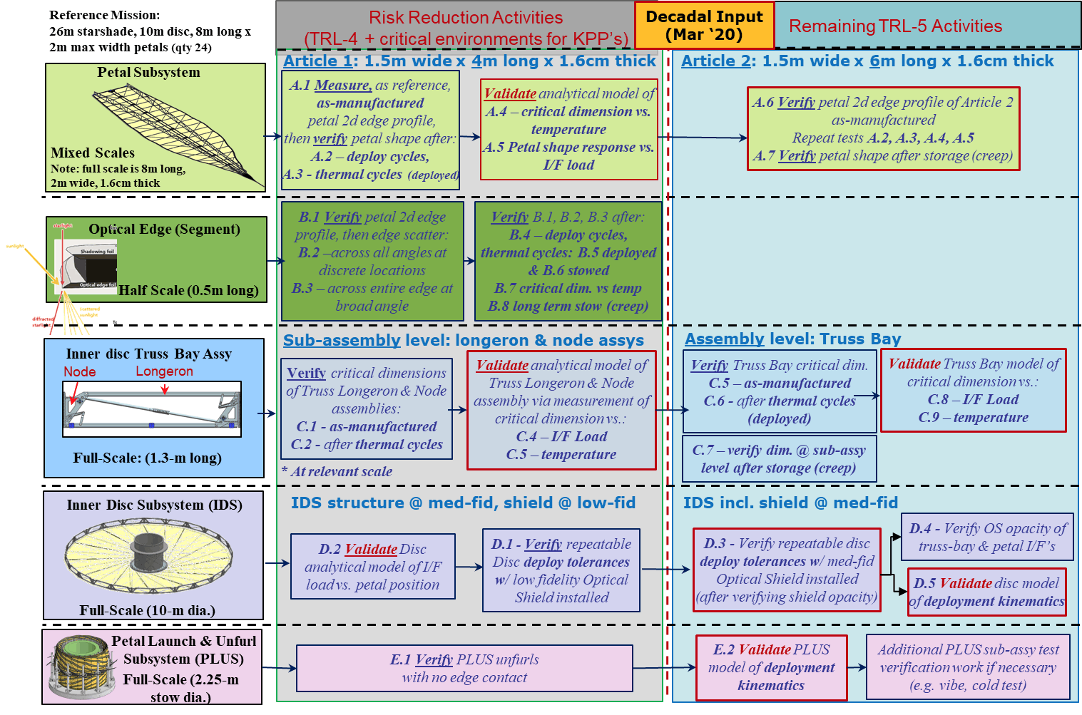
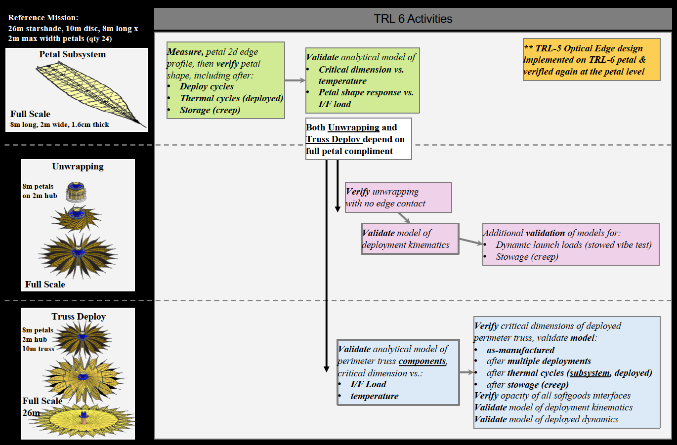
| Starshade Petal Position Accuracy and Stability |
Deploy and maintain petal position accuracy in L2 environment |
11.2.1.1 |
- Petal position deployment tolerance (≤150 µm) verified with multiple deployments of 12 m flight-like perimeter truss and no optical shield
- No environmental testing
|
- Petal position deployment accuracy on 20 m perimeter truss: ±600 µm (3σ) bias
- Position stability in operational environment: ±400 µm (3σ) random
|
4 |
5 |
| Starshade Petal Shape Accuracy and Stability |
Starshade petal shape maintained after deployment, thermal at L2 |
11.2.1.2 |
- Manufacturing tolerance (≤100 µm) verified with low fidelity 6 m long by 2.3 m prototype; No environmental tests
- Petal deployment tests conducted on prototype petals to demonstrate rib actuation; No post-deploy cycle and petal shape stability measurements
|
- Petal 16 m long by 4 m wide
- Petal shape manufacture: ±140 µm (3σ)
- Post-deploy cycle and petal shape thermal stability ≤ ±160 µm (3σ)
|
4 |
5 |
| Starshade Scattered Sunlight for Petal Edges |
Limit edge-scattered sunlight and diffracted starlight with petal optical edges |
11.2.2.1 |
- Chemically etched amorphous metal edges limit solar glint flux to 25 visual magnitudes in two main lobes, verified at coupon level
- In-plane shape tolerance of ±20 µm met at half meter length after integration onto prototype petal
- In plane shape stability demonstrated post-deploy and thermal cycle
- Scatter performance on half meter edge verified post environment
|
- One meter length edges assembled precisely onto petal
- Petal edge in-plane shape tolerance: ±66 μm (3σ)
- Petal edge in-lane placement tolerance: ±55 μm (3σ)
- Solar glint: 26.25 (TBR) visual magnitudes in two main lobes
|
4 |
5 |
| Starshade Contrast Performance Modeling and Validation |
Validate at flight-like Fresnel numbers the equations that predict the contrasts |
11.2.2.2 |
- 1.5 × 10⁻¹⁰contrast demonstrated at Fresnel NumberR=1 ~13 (monochromatic)
- Expect 1 × 10⁻¹⁰ contrast demonstrated at Fresnel NumberR=1 ~13 (10% bandwidth) in March 2019
|
- Experimentally validated models with scaled flight-like geometry and Fresnel NumberR=1 ≥12 across a broadband optical bandpass. Validated models are traceable to 1 × 10⁻¹⁰ contrast system performance in space
|
4 |
5 |
| Starshade Lateral Formation Sensing |
Lateral formation flying sensing to keep telescope in starshade’s dark shadow |
11.2.3.1 |
- Simulations have shown centroid to ≤1/10th aperture with ample flux to support control loop
- Control algorithms demonstrated control ≤1 m radius within line of sight of the star for durations representative of typical starshade observation times
|
- Demonstrate sensing lateral errors ≤0.40 m accuracy (≤1/10th aperture) at scaled flight separations
- Control algorithms demonstrated with scaled lateral control corresponding to ≤1 m of the line of sight
|
5 |
5 |
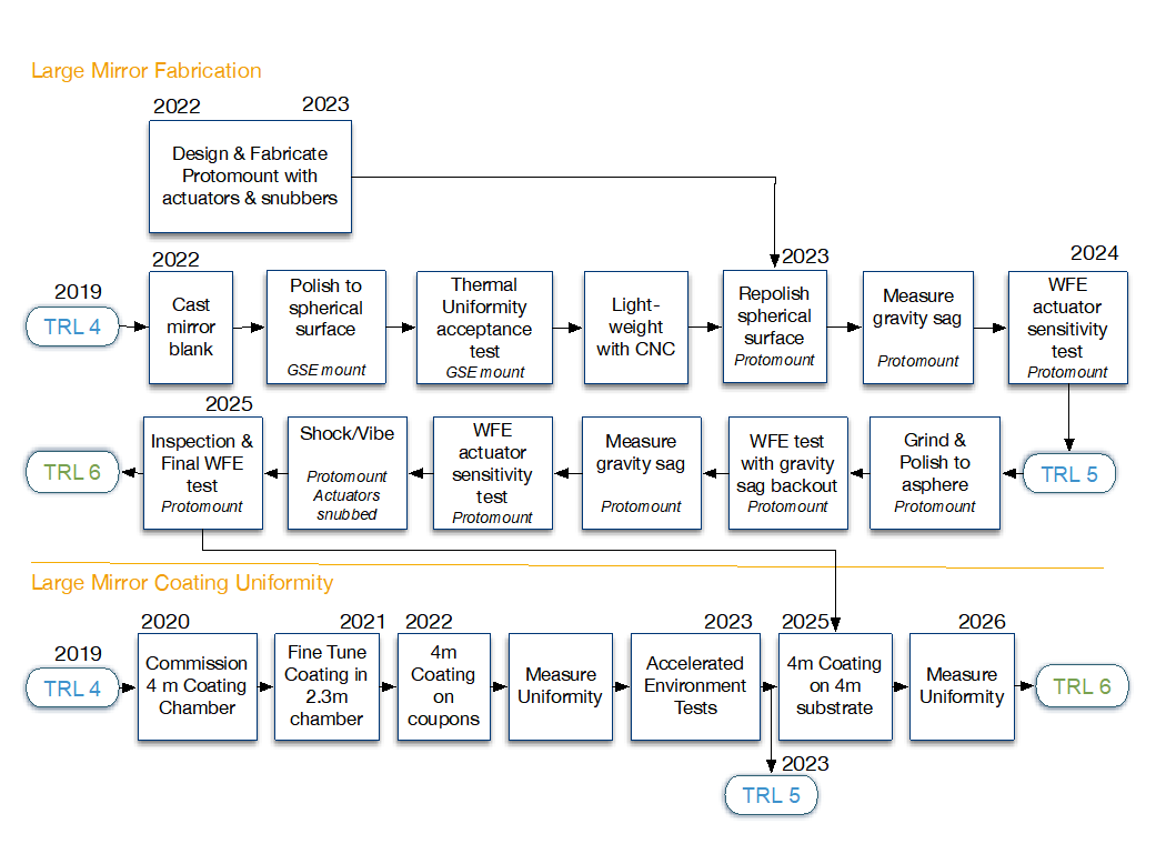
| Large Mirror Fabrication |
Large monolith mirror that meets tight surface figure error and thermal control requirements at visible wavelengths |
11.3.1.1 |
- 4.2 m diameter, 420 mm thick blanks standard
- Schott demonstrated computer-controlled-machine lightweighting to pocket depth of 340 mm, 4 mm rib thickness on E-ELT M5 and 240 mm deep/2 mm thick rib on Schott 700 mm diameter test unit
- State-of-the-practice (SOP) lightweighting has yielded large mirrors of aerial density 70 kg/m2
- Zerodur® can achieve 2.83 parts per billion/K CTE homogeneity (DKIST mirror)
- Wavefront stability: 25 nm rms for HST in LEO
Wavefront Error of WFIRST-like primary mirror (spatial frequency cycles/beam diam. : nm RMS):
- 0-7 cy/D: 6.9 nm RMS
- 7-100 cy/D: 6.0 nm RMS
- >100 cy/D: 0.8 nm RMS
|
- 4.04 m diameter substrate
- 3–4 mm ribs, 14 mm facesheet, and pocket depth of 290 mm for 400 mm thick blank
- Aerial density 110 kg.m2
- < 5 ppb/K CTE homogeneity
- First mode ≥60 Hz
- Wavefront stability of 100s to a few picometers rms (depending on spatial frequency) over 100s of seconds
- Wavefront Error (spatial frequency cycles/beam diam. : nm RMS):
- 0-7 cy/D: 6.9 nm RMS
- 7-100 cy/D: 6.0 nm RMS
- >100 cy/D: 0.8 nm RMS
|
4 |
4 |
| Large Mirror Coating Uniformity |
Mirror coating with high spatial uniformity over the visible spectrum |
11.3.1.2 |
- Reflectance uniformity <0.5% of protected Ag on 2.5 m TPF Technology Demonstration Mirror
- IUE, HST, and GALEX used MgF2 on Al to obtain >70% reflectivity from 0.115 µm to 2.5 µm
- Operational life: >28 years on HST
|
- Reflectance uniformity <1% over 0.45–1.0 µm
- Reflectivity comparable to HST:
- 0.115–0.3 µm: ≥70 %
- 0.3 – 0.45 µm: ≥88%
- 0.45 – 1.0 µm: ≥85 %
- 1.0 - 1.8 µm: ≥90 %
- Operational life >10 years
|
4 |
4 |
| Laser Metrology |
Sensing for control of rigid body alignment of telescope front-end optics |
11.3.2.1 |
- Thermally stabilized Planar Lightwave Circuit fully tested
- Nd:YAG ring laser and modulator flown on LISA-Pathfinder
- Phase meters flown on LISA-Pathfinder and Grace Follow-On
- Sense at 1 kHz bandwidth
- Uncorrelated per gauge error of 0.1 nm
- Laser Met System at JPL expected TRL 6 by 9/19
|
- Sense at 100 Hz bandwidth
- Uncorrelated per gauge error of 0.1 nm
|
5 |
5 |
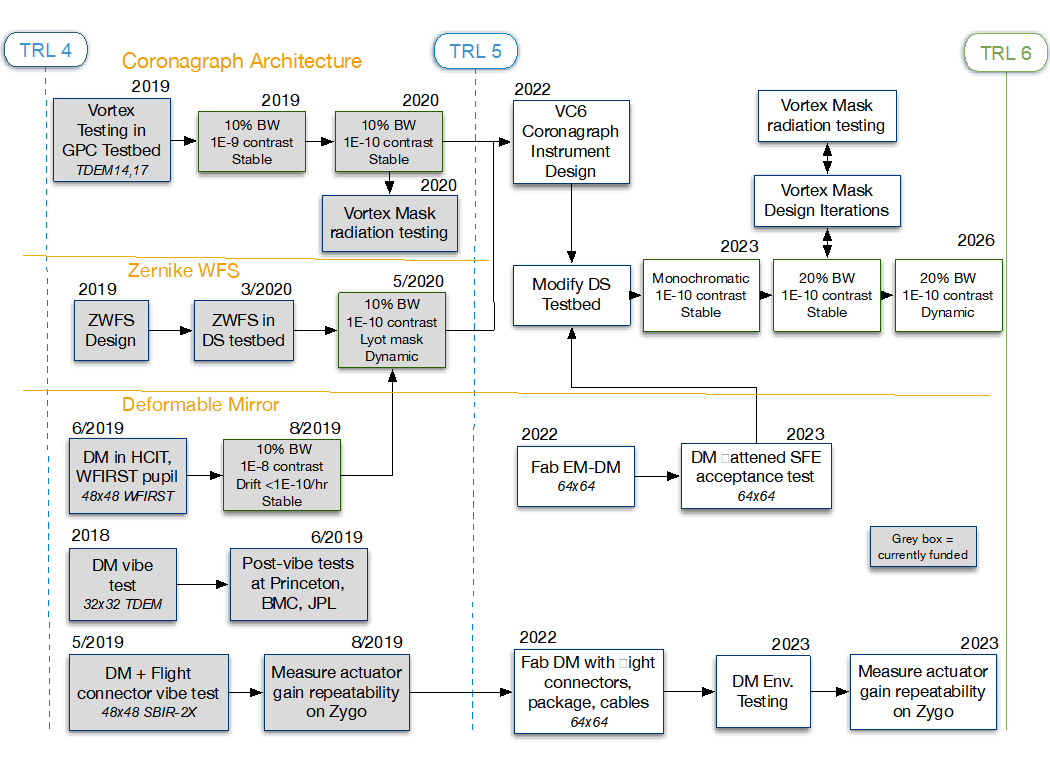
| Coronagraph Architecture |
Suppress starlight by a factor of ≤1E-10 at visible and near-IR wavelengths |
11.4.1.1 |
- Hybrid Lyot: 6 × 10⁻¹⁰ raw contrast at 10% bandwidth across angles of 3–16 λ/D demonstrated with a linear mask and an unobscured pupil in a static vacuum lab environment
- Vector vortex charge 4: 5 × 10⁻¹⁰ raw contrast monochromatic across angles of 2–7 λ/D
- Lyot: 3.6 × 10⁻¹⁰ raw contrast at 10% bandwidth over 3–7 λ/D in a static lab environment (DST)
- Vector vortex charge 6: 8.5 × 10⁻⁹ coherent contrast at 10% bandwidth across angles of 3–8 λ/D demonstrated with an unobscured pupil in a static lab environment
|
- Vortex Charge 6
- Raw contrast of ≤1 × 10⁻¹⁰
- Raw contrast stability of ≤2 × 10-11
- Inner working angle (IWA) ≤ 2.4 λ/D
- Coronagraph throughput ≥10%
- Bandwidth ≥20%
|
4 |
5 |
| Zernike Wavefront Sensing and Control (ZWFS) |
Sensing and control of low-order wavefront drift; monitoring of higher order Zernike modes |
11.4.2 |
- <0.36 mas rms per axis LoS residual error demonstrated in lab with a fast-steering mirror attenuating a 14 mas LOS jitter and reaction wheel inputs on Mv = 5 equivalent source; ~26 pm rms sensitivity of focus (WFIRST Coronagraph Instrument Testbed)
- WFE stability of 25 nm/orbit in low Earth orbit (HST). Higher low-order modes sensed to 10–100 nm WFE rms on ground-based telescopes
|
- LoS error <0.2 mas rms per axis
- Wavefront stability:≤~100 pm rms over 1 second for vortex
- WFE <0.76 nm rms
|
4 |
5 |
| Deformable Mirrors |
Flight-qualified large-format deformable mirror |
11.4.3 |
- Micro-electromechanical DMs available up to 64 × 64 actuators, 400 µm pitch with 6 nm RMS flattened WFE; 3.3 nm RMS demonstrated on 32 × 32 DM
- 8.5 × 10⁻⁹ coherent contrast at 10% bandwidth in a static test achieved with smaller 32 x 32 MEMS DMs
- Drive electronics in DST provide 16 bit resolution which contributes ~1 × 10⁻¹⁰ to contrast floor
|
- 64 × 64 actuators
- Enable coronagraph raw contrasts of ≤1 × 10⁻¹⁰ at ~20% bandwidth and raw contrast stability ≤2 × 10-11
- <3.3 nm RMS flattened WFE
- Drive electronics of at least 18 bits
|
4 |
5 |
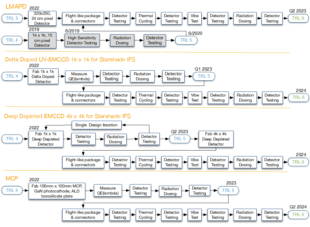
| Delta Doped UV and Visible Electron Multiplying CCDs |
Low-noise UV and visible detectors for exoplanet characterization |
11.5.1.1 |
- 1k × 1k EMCCD detectors (WFIRST)
- Dark current of 7 × 10⁻⁴ e-/px/s
- CIC of 2.3 × 10⁻³ e-/px/fram
- Read noise ~0 e- rms (in EM mode)
- Irradiated to equivalent of 6-year flux at L2
- Updated design for cosmic ray tolerance under test
- 4k × 4k EMCCD fabricated (update with test specifics)
|
- 0.45–1.0 µm response;
- Dark current <10-4 e-/px/s
- CIC < 3 × 10⁻³ e-/px/fram
- Effective read noise <0.1e- rms
- Tolerant to a space radiation environment over mission lifetime at L2
- 4k × 4k format for Starshade IFS
|
4 |
5 |
| Deep Depletion Visible Electron Multiplying CCDs |
Low-noise detectors with improved QE at 940 nm for exoplanet characterization |
11.5.1.1 |
- Under investigation. e2V claims dark current is on boundary surface and not throughout volume
- CCD-201 is not currently made in deep depletion
- CCD-220 (regular CCD) dark current < 0.02 e-/px/s
|
- QE >80% at 940 nm
- thicker silicon (up to 200 µm thick layer), deep depletion devices
- 4k × 4k format for Starshade IFS
|
4 |
4 |
| Linear Mode Avalanche Photodiode Sensors |
Near infrared wavelength (0.9 µm to 2.5 µm), extremely low noise detectors for exo-Earth IFS |
11.5.1.2 |
- HgCdTe photodiode arrays have read noise <~2 e- rms with multiple non-destructive reads; dark current <0.001 e-/s/pix; very radiation tolerant (JWST)
- HgCdTe APDs have dark current ~ 10–20 e-/s/pix, read noise <<1 e rms, and < 1k × 1k format
- LMAPD have 0.0015 e-/pix/s dark current, <1 to 0.1 e rms readout noise (SAPHIRA) for 320×256, 24 µm pixels
|
- Read noise <<1 e- rms
- Dark current <0.002 e-/pix/s
- In a space radiation environment over mission lifetime
- 320 × 256 pixel array, 24 µm pixels
|
5 |
5 |
|
|
|
- LMAPD 1k × 1k formats of 15 µm pixels have << 1 e- rms read noise at gain of 25, full testing begins summer 2019
|
- 1k × 1k pixel array, 15 µm pixels
|
4 |
5 |
| UV Microchannel Plate (MCP) Detectors |
Low-noise detectors for general astrophysics as low as 0.115 µm |
11.4.4 |
- MCPs: QE 44% 0.115–0.18 µm with alkalai photocathode, 20% with GaN; dark current ≤0.1–1 counts/cm2/s with ALD activation and borosilicate plates
|
- Dark current <0.001 e-/pix/s (173.6 counts/cm2/s), in a space radiation environment over mission lifetime,
- QE>50% (TBR) for 0.115–0.3 µm wavelengths
|
4 |
4 |
| Microthrusters |
Jitter is mitigated by using microthrusters instead of reaction wheels during exoplanet observations |
11.6.1.1 |
- Colloidal microthrusters 5–30 µN thrust with a resolution of ≤0.1 µN, 0.05 µN/√Hz, 100 days on orbit on LISA-Pathfinder
- Colloidal microthrusters with 100 µN thrust and 10 year lifetime under development
- Cold-gas micronewton thrusters flown on Gaia (TRL 9), 0.1 µN resolution, 1 mN max thrust, 0.1 µN/sqrt (Hz), 4 years of on-orbit operation
|
- Thrust capability: 350 µN with 16 thruster cluster
- Thrust resolution 4.35 µN
- Thrust noise: 0.1 µN/√Hz
- Operating life: 5 years
|
5 |
5 |